.png?width=250&height=76&name=ATAG%20Logo%20(72dpi%20RGB).png "Atag")
The boiler incorporates a built in frost thermostat which automatically turns on the boiler and pump if the water in the boiler falls below 5°C, providing the electrical supply is on. The boiler will operate until the water temperature in the system reaches approximately 10°C measured on the flow sensor in the boiler.
Any other pipework outside of the boiler should be protected from the risk of freezing and protected with insulation. Additional protection from external frost thermostat and pipe thermostat should also be considered.
If a customer has a series A, S or Q, this means this boiler is a commercial boiler. For all queries regarding commercial boilers contact ATAG Commercial on 01268 546770 or visit www.atagcommercial.co.uk
During winters the UK has experienced prolonged spells of extremely cold weather – down to minus 15°C in some areas. This resulted in a significant increase in the number of calls to boiler manufacturers and heating installers from householders with condensing (high efficiency) boilers where the condensate drainage pipe had frozen and become blocked with ice, causing boiler shutdown. In the vast majority of cases, problems occurred where the condensate drainage pipe was located externally for some part of its length.
Due to the cold weather our ATAG boilers can show a fault code 133 or 501(No flame after 5 attempts) due to the condensate pipe freezing, as a result of the condensate not being able to run away from the boiler and the boiler to eventually come up with a fault code 133 or 501 due to that fact.
The condensate pipe can be thawed by applying a hot water bottle, a microwaveable heating pack (the sort used for muscular aches and pains) or cloths soaked in warm water to the exterior of the pipe, close to the likely point of blockage. Warm water can also be poured onto the pipe from a watering can or similar container. Do not use boiling water. Note: You should not attempt to thaw a condensate drain pipe if you cannot easily reach it from ground level. Be aware that any water used can quickly freeze if it falls onto pathways – causing a possible slip hazard.
In most cases, once the condensate drain pipe is cleared and a reset has been carried out, the boiler will re-ignite using its automatic operating sequence.
The Heating and Hotwater Industry Council (HHIC) have also published guidance for householders on frozen condensate drainage pipes.
Is your One Zone control not connecting to your Wi-Fi, but the rest of your home is?
Most home routers can broadcast a Wi-Fi in one of two frequencies; 2.4Ghz and 5Ghz. Newer routers use a combined or “Synchronised” frequency, which merges both frequencies into one. The One controller only works on a 2.4Ghz frequency.
See how to resolve this issue here
The boiler does not require any air vents for cooling in the room in which it is installed or when installed in a cupboard or compartment. The minimum clearances for servicing must always be maintained.
Note: A cupboard or compartment used to enclose the boiler must be designed and constructed specifically for the purpose,
i.e. comply with the Building Regulations.
When the boiler is not required to heat the system anymore, the pump will continue to run for 60 seconds, so heat can be dissipated around the system.
(Note: Regular boiler only. The pump must be wired into the pump connections on the boiler)
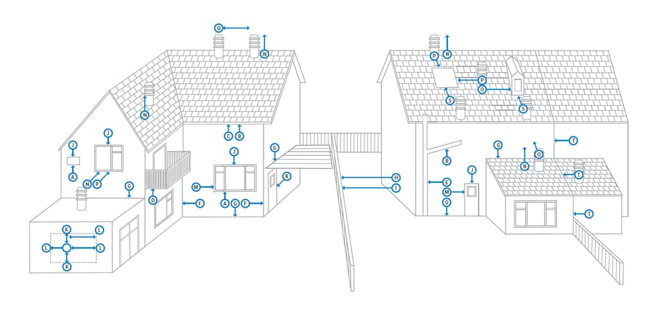
| Terminal Position | Min distance (mm) | |
|---|---|---|
| A | Directly below an opening, air brick, windows, etc. | 300 (See Note 1) |
| B | Below gutters, soil pipes or drain pipes | 75 (See Note 3) |
| C | Below eaves | 200 (See Note 3) |
| D | Below balconies | 200 (See Note 3) |
| E | From a vertical drain pipe or soil pipe | 150 (See Note 3) |
| F | From an internal or external corner | 300 (See Note 2) |
| G | Above ground, roof or balcony level | 300 |
| H | From a surface or boundary facing the terminal | 600 (See Note 4) |
| I | From a terminal facing the terminal | 1200 |
| J | Above an opening, air brick, window etc. | 300 (See Note 1) |
| K | Vertically from a terminal on the same wall | 1500 |
| L | Horizontally from a terminal on the same wall | 300 |
| M | Horizontally from an opening, air brick, window etc. | 300 (See Note 1) |
| N | Minimum protrusion through a roof | 300 |
| O | From a vertical obstruction | 300 |
| P | From an openable window | 600 |
| Q | From an adjacent vertical terminal | 300 |
| R | From an opening in the car port (e.g. door, window) into the dwelling | 1200 |
| S | Below a roof window | 2000 |
| T | Terminal parallel to a boundary | 300 |
Notes:
- In addition, the terminal should not be nearer than 150mm to the framework of an opening into the building, i.e. a window surround or door surround.
- This clearance may be reduced to 25mm without effecting the performance of the boiler. However, to ensure the condensate plume does not affect adjacent surfaces a clearance of 300mm is preferable.
- These clearances may be reduced to 25mm without affecting the performance of the boiler. However, to ensure the condensate plume does not affect adjacent surfaces the terminal can be extended beyond gutters, pipes, eaves, balconies etc. by up to 500 mm. If the flue is extended more than 500mm outside, it should be boxed and insulated.
- To reduce the possibility of nuisance to neighbouring buildings etc. it is recommended the terminal should not be less than 2500mm from car parking spaces, building boundary walls, fences etc.
- A terminal must not be sited under a car port roof.
- In certain weather conditions the terminal will emit a plume of steam. If possible avoid positioning the terminal where this may cause a nuisance, i.e. positions A, D, G, H, J or M.
- The flue terminal must be exposed to the external air and the position must allow the free passage of air across it at all times.
- A terminal must not be sited below 2m where people have access to, such as public footpaths, access routes, patios etc. However, if the terminal is fitted less than 2m above a surface where there is no public access, the terminal must be protected by a terminal guard.
Error code 118 could mean that the system pressure is too low and you may see that the system pressure gauge indicates that the pressure in the system is below the 1 bar pressure.
The pressure within the system can be seen in two ways. There is an analogue gauge, which can be found under the bottom left hand side of the boiler or you can find a digital reading from the digital display of the control panel. The digital display can be seen by pressing the Eco button for 6 seconds and then scroll through (tap + plus button) to ‘A6’ which will display the water pressure.
The system pressure should be set around 1.0 – 1.2 bar when the water is cold.
When the system is working and the water is heated up within the system, water expands due to heat and you may see the pressure rise up to around 1.8 – 2.4bar when hot. This is normal as water system pressure increases due to heat.
So we are looking for the system pressure to be set around 1.0 – 1.2 bar when the water is cold.
Turn off any clocks and room thermostat for heating or hot water controls.
On the iC and iC Economiser Plus models, to re-pressurise the system you will need to find the filling loop (copper ‘U’ shaped tube with two nuts at each end). On the underside of the boiler there is a filling loop position where this copper ‘U’ shaped tube will connect between the small blue and black isolation valve connection. If not in position, remove the caps and install as shown and tighten up the nuts hand tight.
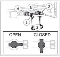
The taps should be opened a quarter of a turn and the water will start to refill the system (water should be heard filling the system). You should see the pressure gauge rise back up between 1 bar and 1.2 bar pressure and then stop filling. The error code 118 will stop and the boiler will now operate. If the error code 118 is still active, fill up the system a little more but not over 1.5bar.
The display should now show ‘OK’, which means the pressure level is correct and the boiler is ready to operate.
(If you do fill the system too much and the pressure gauge is too high, just bleed water from a radiator until the pressure on the gauge goes down to below 1.2 bar).
-
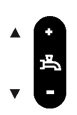
Setting of hot water temperature
+/- function (iC Range only)
(ancillary function: Scroll and +/- function) -
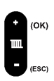
Setting of boiler temperature
(max flow temperature) +/- function
(ancillary function: OK and escape) -
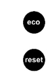
Eco-function DHW on/off. (iC Range only)
Press for 6 seconds for boiler informationReset Button
-
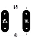
Commissioning function (Do not use. For service purposes only)
Pump function (Press both – buttons for 6 seconds) (iC & iS-Range only)
-
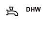
Visible when DHW program is active
Flashing when there is a heat demand for DHW (iC Range only) -
Visible when heating program is active
Flashing when there is a heat demain for heating -
Visible when boiler is active for heating or DHW
-

Visible when DHW comfort function is not active
-
Error indication (accompanied with a code)
-
Service-mode or blocking
-
Visible when pump is set to continuously
Flashing when frost program is active (iC & iS Range only)
Error Codes
Blocking Code with spanner symbol 
Error is temporary and will clear itself or will lock the boiler after several attempts (error)
Error Code with bell symbol 
Boiler is locked and can only be remedied by a reset and/or intervention by a service technician
| 10 | Outside sensor error | 111 | Maximun pressure exceeded |
| 20 | Flow sensor error | 117 | Pressure too high (> 3 bar) or pump pressure increase too high (iC & iS Range only) |
| 40 | Return sensor error | 118 | Pressure too low (< 1 bar) or pump pressure increase too low) no pump detection) (iC & iS Range only) |
| 50 | DHW sensor error (iC-Range only) | 119 | Link on X2 position 4 and 5 missing |
| 61 | Bus communication error | 129 | Fan error (fan does not start up) |
| 78 | Water pressure out of range | 133 | No flame after 5 ignition attempts |
| 105 | Venting program active when power turned on or interupted (runs approx. 7 mins) | 151 | Fan error (speed control is not achieved or is out of range) or control unit defective |
| 110 | Safety temperature exceeded | 154 | Flow temperature increases to fast, return > flow |
ErP stands for ‘Energy related Products’, and is a mandatory piece of legislation, created to help achieve targets set for energy consumption, with the goal being to reduce consumption by 20% and increase the share of renewable energies by 20% by 2020.
The regulation is set up by the European Union
The new directive is designed to help inform homeowners about the efficiency of the heating and hot water products they are buying, by displaying a simple energy label that categories the product according to its efficiency.
The National Measurements & Office (NMO) will be responsible for ensuring compliance. The ErP requirements are also likely to be included in Part L of the Building Regulations.
Space and water heating products will be required to have an energy label, already familiar on other white goods, such as A+++ rated dishwashers and washing machines. Low-rated water heating products (such as those which might have been rated in bands F or G) will not be permitted after the 26th September.
It is not an offence for a merchant to sell a product without an ErP label after the 26th September 2015, as long as that item was in stock prior to that date.
No, a single generator and a hot water cylinder do not require a package label.
A package label is only used if you are supplying new components. If you are simply replacing a boiler or heat pump and using existing controls then you are not required to provide a package label.
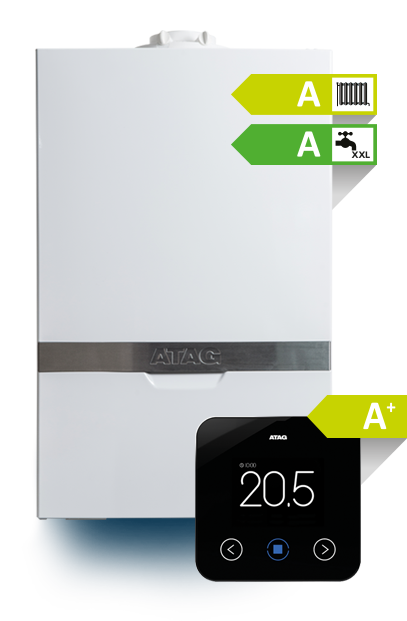
Installers will be responsible for providing the energy labelling for a complete heating system eg if a heating engineer installs an ATAG iC28 combination boiler alongside the ONE controller, the installer will have to calculate the overall system efficiency – which in this case would be 98% or A+ rated.
To calculate the overall efficiency of the heating system, you must record each product on a document known as a product fiche.
A product finche is a table of technical information that a manufacturer, such as ATAG Heating Technology, is required to provide for each individual product.
ATAG is on hand to help their network of installers with any questions relating to the ErP Directive. This includes setting up a helpline, on 0800 254 5065 and an ErP calculator, which is available from the approved ATAG installer portal.